UPDATE (From Sebastian): If you choose to make a lower from Delrin, you’re safest using Food Grade Delrin, which is highly x-ray detectable. While I believe ordinary Delrin should be dense enough to be detectable by the modern equipment used for airport screening, it is unlawful to make a firearm, the major component (which includes the receiver) does not show its true shape on the types of x-ray equipment commonly used for airport screening. Be careful about the types of plastic you choose. Jason did not mention this in the original post, but I am updating now as a warning. You are responsible for compliance with federal law.
After finishing the aluminum bolt together lower, I went back to trying to make a single piece lower out of Delrin.
The process described below is my third attempt. In the first two I had alignment problems which made the right and left sides not quite match up and gave an egg shape to some of the holes.
I also switched from PyCAM to Deskproto. While the people working on PyCAM have done a nice job so far, it needs more work. For the kind of things I do its just barely useable. Deskproto has all the things that drive me nuts in PyCAM fixed, and while its commercial, the cost, especially for a hobby license, is quite reasonable (less than an AR-15 parts kit) and it doesn’t use any nasty DRM, so after you’ve purchased it you don’t have to get permission from the mother ship to reinstall it or install it on a different computer.
In Deskproto, I added support bridges to the model that run through the buffer tube hole and magazine well.
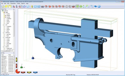
This way I could use the outside edges of the Delrin block for holding down the part while machining the left and right sides, but don’t need to do extra machining steps later to remove the supports.
Update: The 3d model of the lower is originally from www.cncguns.com.
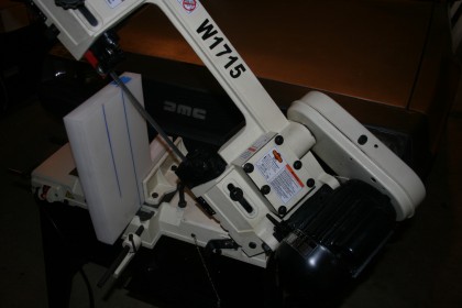
I used an inexpensive Chinese import band saw to cut the block of Delrin down to an appropriate size….
Then bolted the block down on the mill and started machining the right side.
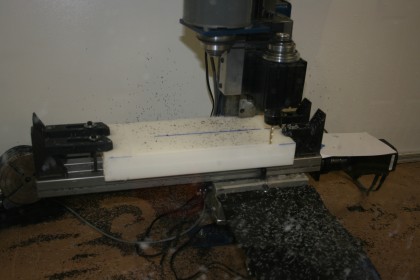
I did a roughing pass with a 1/4 inch flat end mill, and contouring pass with the same 1/4 inch flat end mill, a contouring pass with a 18 inch flat end mill, and then a finishing/polishing pass with a 1/8 inch ball nose end mill.
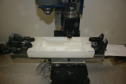
Next I milled a slot along the back and top of of the block that went almost all the way through the block, and then used the band saw to cut away the excess material beyond the slots. Since I know the exact location where it milled the slots, this gave me good surfaces for aligning things when I flipped the block over.
Here is the block flipped over and mounted back on the mill.
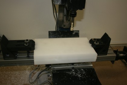
Next I did the same procedure on the right side for the left side. What you don’t see from the other pictures is that the process is rather messy. Here is what things looked like before I vacuumed up the debris.
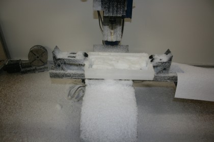
and cleaned up…
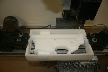
Now back to the band saw to cut the outside frame away from the part. Next was the buffer tube mount hole. The Taig mill in its default configuration doesn’t have enough clearance in the Z direction for the lower to fit with its back surface perpendicular to the spindle, but it turns out that is easy to fix. If you loosen one bolt the whole spindle assembly slides off.
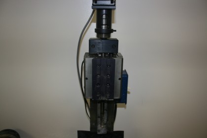
You can then unbolt the mounting plate and bolt it back on higher up.
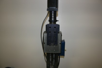
Then slide the spindle back on the mounting plate, and keeping it as high as possible tighten the dovetail bolt. Now there is enough clearance for the lower and and a vise to fit.
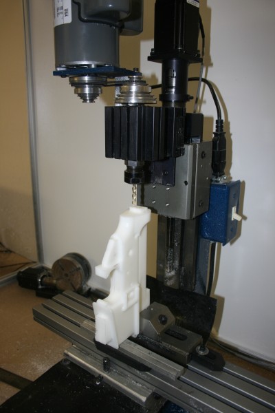
The lower was held in place by clamping the vise down on the remnants of the support bridges. They provide a nice flat surface and there is no risk of scratching or damaging the lower.
After machining the buffer tube mount hole..
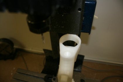
Next was the bottom half of the magazine well and the slots for the trigger guard. Again the lower is held is place by the remnants of the support bridges.
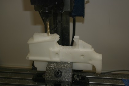
While the lower was mounted upside down I took the opportunity to drill the hole for the selector spring. Then I used the band saw to cut off most of the remaining support bridges, and positioned the lower right side up for machining the top half of the magazine well and the fire control area. There isn’t enough support material left to provide a clamping place, but the trigger guard area has a flat surface that can be used.
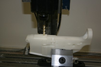
At this point the lower is finished, except for a few holes that need to be drilled.
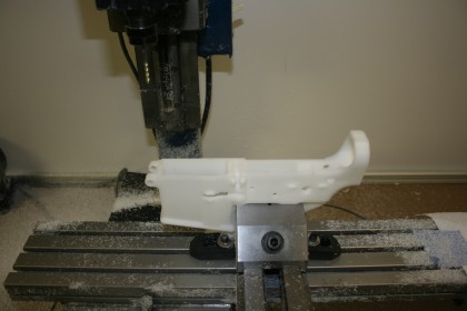
First I did the hole for the front take down pin spring.
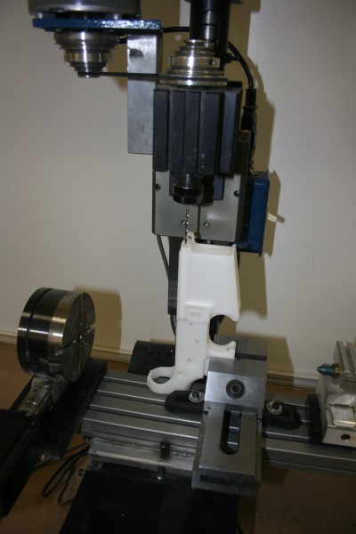
Then I tried the bolt catch hole.
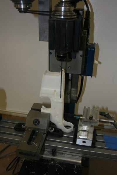
But it turns out you can’t drill that hole from the front. The bulge in the magazine well gets in the way.
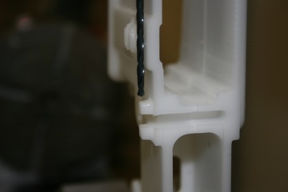
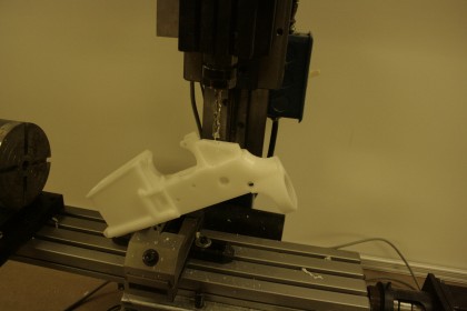
You have to go in from the back. I should have drilled this hole while I was machining the buffer tube mount hole. Now without the support bridges there isn’t a good way to mount the lower with the front facing down. But by moving the spindle mounting place I was able to do this…
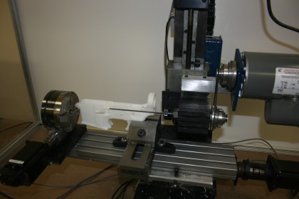
and drill the hole.
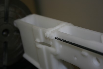
Next came the rear take down pin spring hole.
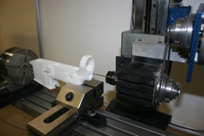
Then the trigger guard holes.
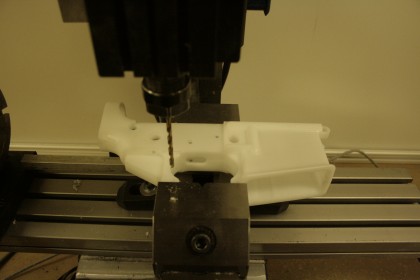
And finally the hole for the pistol grip.
Here is the fully assembled lower..
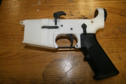


The amusing thing about this is that hunk of plastic is now a “firearm” both under federal law and state law. I doubt Jason wants to part with his creation for that to matter, but even if you wanted to sell a home made firearm one day, I’m not sure how you would transfer a firearm that has no serial number. I think it’s probably legal, but I doubt you’ll find a dealer willing to try it.
Gotta serial number it to transfer it.
From the JBT’s website: “Individuals manufacturing sporting-type firearms for their own use need not hold Federal Firearms Licenses (FFLs). However, we suggest that the manufacturer at least identify the firearm with a serial number as a safeguard in the event that the firearm is lost or stolen. Also, the firearm should be identified as required in 27 CFR 478.92 IF [emphasis added] it is sold or otherwise lawfully transferred in the future.”
http://www.atf.gov/firearms/faq/firearms-technology.html (right above the question about glock 18 conversions)
I’m jealous. I wish I had the time and money to set up a shop like that! I may in the future, though…
More proof that gun control, in general, cannot work. Good job, Jason.
Delrin is an amazing plastic, easy to machine, but I think I would still prefer to make that part of aluminum. Delrin is about half the tensile strength of aluminum, and about 20 times more flexible than aluminum. This might be an issue over time, especially with a .223 upper, where continual recoil might start to damage the lower.
This lower is intented for .22lr only. Though I’m toying with the idea of making a Delrin lower with thicker walls (and beefing up the front take down pin area) and seeing how well it holds up with a .223/5.56 upper.
Great job. I’ve been watching your series with interest and a little envy.
Some day…
Does it shoot plastic bullets? They’re invisible to X-rays!!
Can you post up the files you used?
Here they are.
You are AWESOME! I am am tying to get my CNC (self converted mill to CNC) I am currently using MACH 3 to control the mill but I always fall down on how to actually take a drawing and get to the mill. When you do your alumn on can you document some of the software steps you did to get you tool paths, and the end mills used. ALL that really basic stuff you prolly take for granted.
Also it may be cheaper to buy a forging?
receiver
or this one
Sorry I didn’t realize you name was Jason too. :P this is the other place I found that does 0% forge
http://www.dsarms.com/AR15-Lower–7075-T6-Alloy-Forging-Military-Spec/productinfo/1001/
I used these jigs for clamping the forges. http://arlower.ray-vin.com/ar15/drawings.pdf
http://www.arlower.ray-vin.com/disclaimer.htm he has some good instructions
that is looking very very good. I will have to try that trick on my taig for the buffer tube :)
Thanks, this should inspire me to write something
Honestly, why not do this with 7075 aluminum and have a full working lower? Although a big block of aircraft aluminum ain’t as cheap.
There is no need for any painting or finishing (though I probably could get away without painting/anodizing aluminum), and its more scratch resistant than painted aluminum.
Delrin is lighter.
I like the strange look of the white Delrin. You can’t really see it in the pictures, but the lower is translucent. If you hold it up to the light you can see all the internal parts.
The cost for the material in either Delrin or aluminum is a lot less than the cost of an upper, so if I had a .223 or other large round upper looking for a home I’d just make an additional aluminum lower.
You could strengthen the part & reduce machining time quite a bit if you didn’t bother to countour/profile outer surfaces that don’t mate with anything. (What engineers call “out in the air”)
You could also simplify the design by omitting features related to the bolt hold.
No reason to be slavish to a design that was optimized for another material to be machined with dedicated tooling.
Had I known that the bolt catch doesn’t work with .22 upper I would have removed it from the design. But upper for this gun is the first .22 AR-15 I’ve ever seen, and it didn’t arrive in the mail until after I finished the lower.
Heck, I was writing about the general case,since you don’t really need a bolt catch to have a functional lower.
If you want to get to specific optimizations for a .22lr pistol only lower, then why not also leave the buffer tube hole solid? You’d lose the benefit of a harder surface for the .22 mechanism to recoil against, but the bulk structure would be stronger than threading a plug into a thin-walled delrin tube.
Heck, maybe just machine a slight depression on the inside, glue a metal plate there, don’t machine the buffer tube hole, and beef up the structure around it a bit. You’d get the benefit of the hardened surface to push back against the .22 mechanism & a whole lot more structure holding it in place.
I have so got to get a mill….
When machine tools are outlawed, only outlaws will have them.
It’s how control freaks think.
Very Nice Work.I Will Be Watching For The .223 Build Curious To See How It Holds Up.
FYI you can also just make the trigger guard solid like the noveski’s. That should add some over all streagth. You can also make the magwalls thicker as well. and the buffer tube ring.