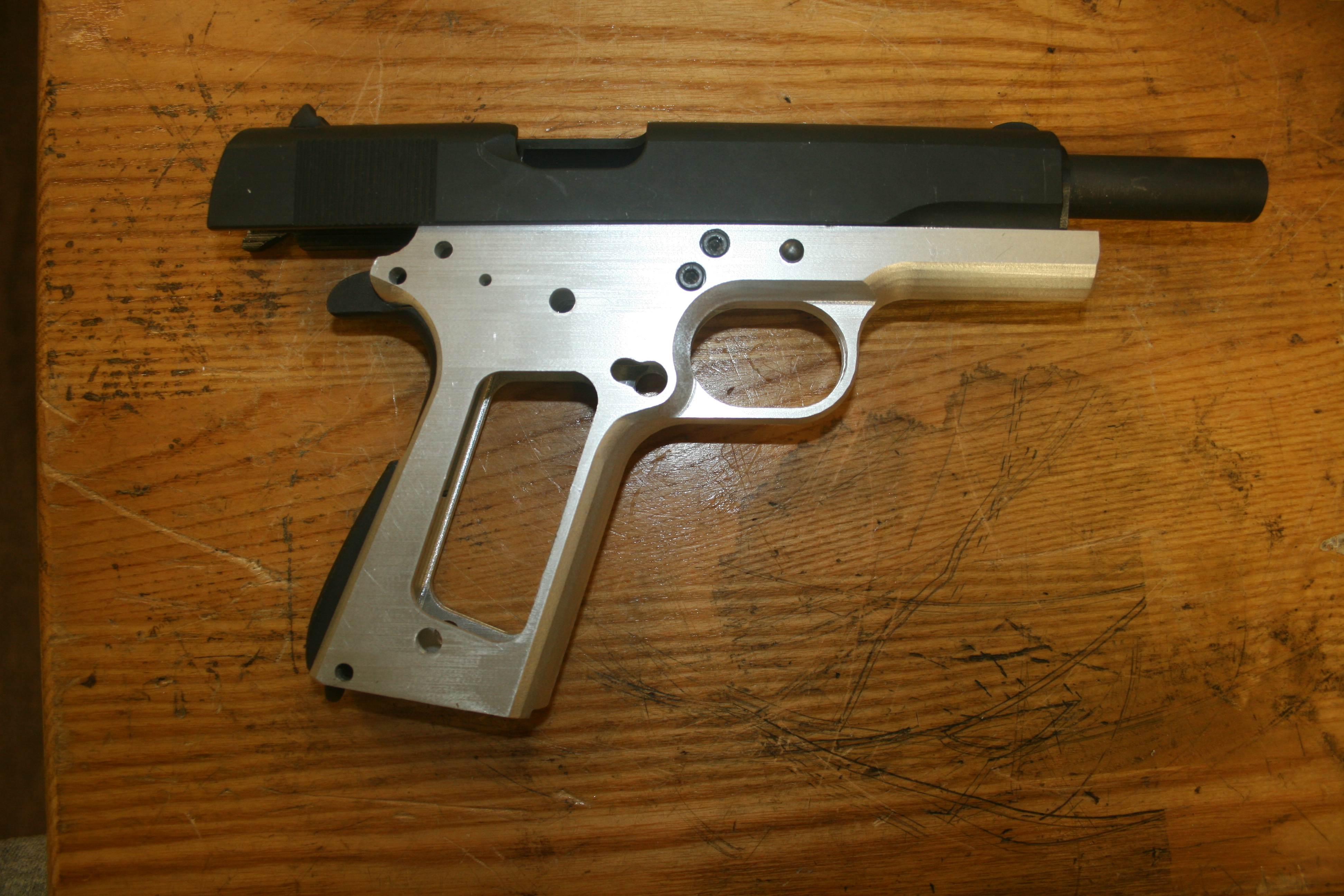
The 1911 frame I made on the CNC machine has been sitting on my workbench for way over a year now. I decided that over Thanksgiving vacation I would finally finish the gun. I only had a couple of small machining operations to do on the top of the frame and then it would be finished. When I made my own AR-15 lowers, once I finished machining the lower receivers according to the CAD model it only took 10 minutes or so to install the parts. I figured I would be able to finish up the frame on Friday, and by Sunday, I’d be ready to go to the range.
It turned out to be not so easy.
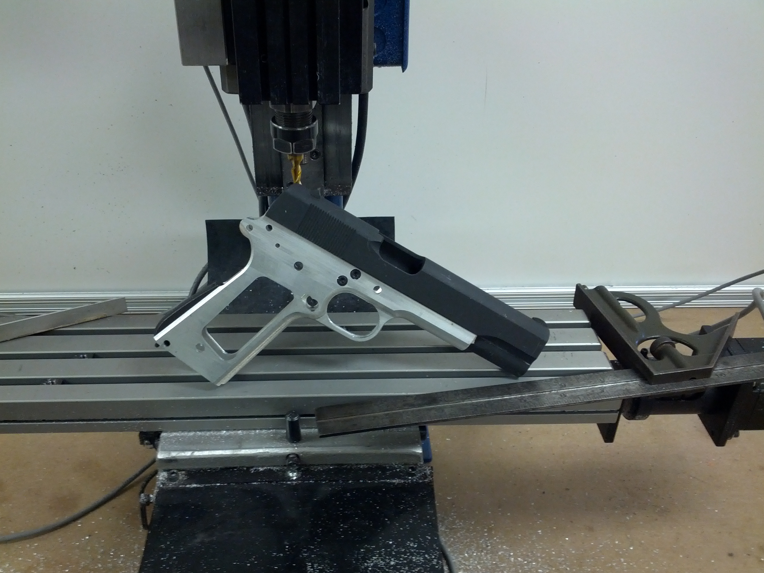
The first problem was that the slide didn’t fit. The slots in the frame weren’t deep enough. After milling out the slots a bit, I was able to fit the slide.

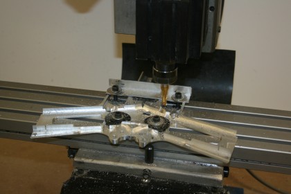
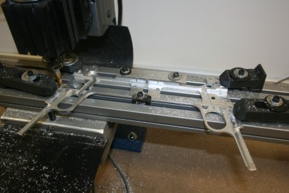
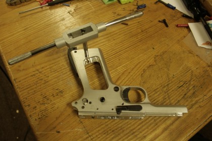
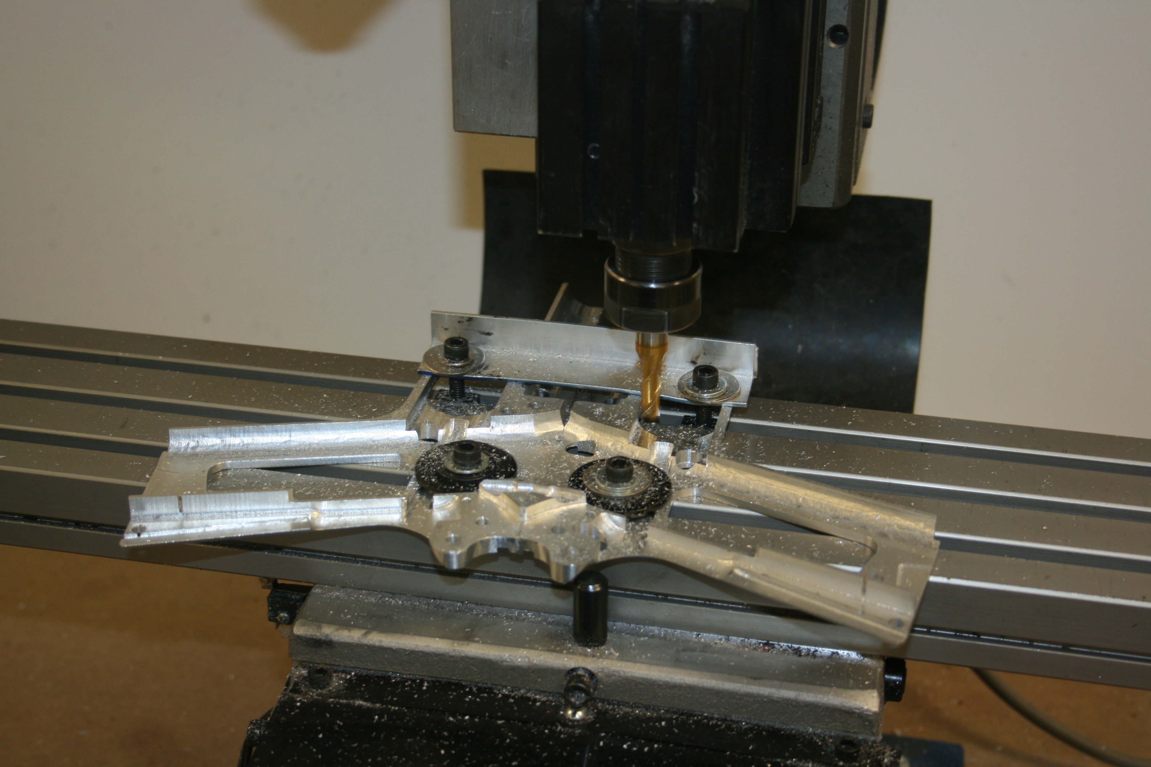
Next, I tried fitting the barrel. With the barrel and associated hardware installed, the slide wouldn’t move. Â As the slide is pulled back, the barrel wasn’t lowering enough for the upper barrel lugs to unlock from the slide. I needed to remove some material from where the bottom barrel lugs hit the frame. From what I can tell, this is normally done going in from the front of the frame with a really long end mill. I don’t have an end mill that long, nor is there enough clearance on my mill to use one on a 1911 frame. But since I had made a two piece frame I was able to unbolt the halves, lie them flat, and go in from the side with a small end mill.
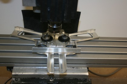
The trick was to remove enough material so that the barrel would go low enough, but not so much that the barrel’s rear motion is stopped by the barrel link. Now the slide and barrel move like they should.
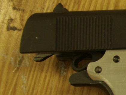
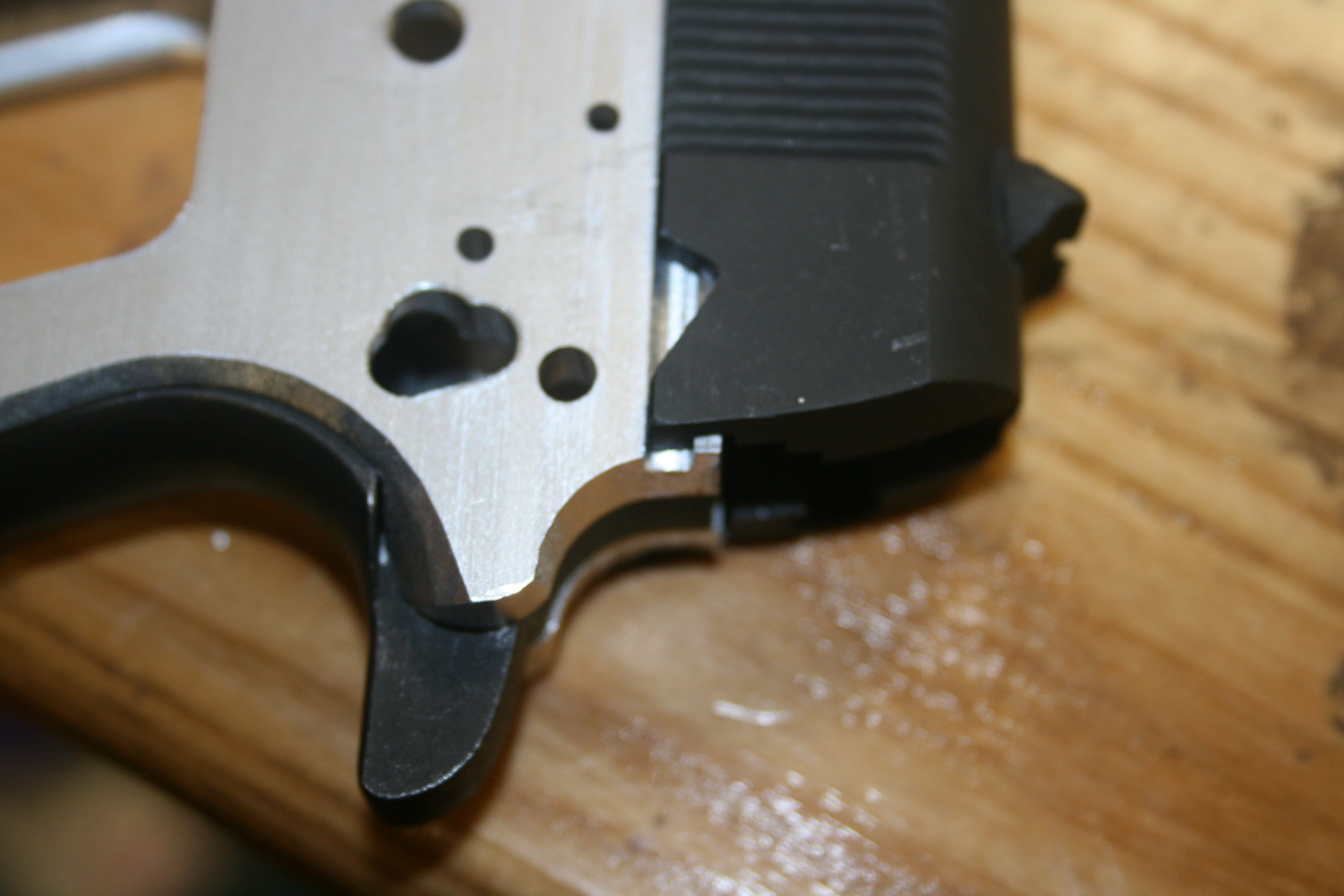
But, with the chamber all the way closed, the slide sits a little forward.

Either the slide, barrel, or frame is slightly off somewhere. I can’t think of an easy way to fix it. It doesn’t seem like it’s going to affect the operation any, so I’m going to leave it as is.
Next came the trigger, which, like the slide, didn’t fit at all. I had to widen the trigger area, again made easy by the fact that the frame can be split into two halves.
After the trigger came the magazine catch, which also didn’t fit. I had to hand file the hole until the magazine catch would drop in. I then discovered that the CAD model I used was missing the slot for the magazine catch lock. I also don’t have any undercutting end mills, so having the slot in the model probably wouldn’t have helped anyway. Since the magazine catch lock is always held against one side of the slot by the spring, I decided to cut a notch from the inside of the frame down to the depth of the slot.

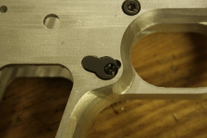
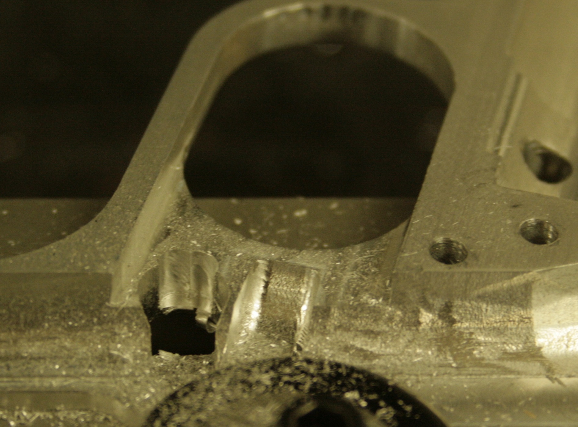
It’s at the point that I almost ruined the frame. I was making the cuts “manually” by using the keyboard to control the mill. While doing so I brushed against the touchpad that I use for a mouse. What I hadn’t realized before is that the touchpad was configured for tap-to-click, so the touch registered as a click, and the mouse pointer happened to be sitting on the feed rate slider. So the feed rate suddenly went from 0.3 in/min to 60 in/min, and the mill went all the way through the frame and almost into the mill table.
Luckily the place where I drilled through isn’t where the tab on the magazine catch lock normally sits, so while the hole doesn’t look all that nice, the magazine catch is still functional.
With the magazine catch installed, I tried to insert a magazine, but it didn’t fit. I had to widen the magazine well.
Now, it was time to install the sear and disconnector. The sear was too wide to fit in the space for the fire control group, so the frame is split and back on the mill again to widen that area a bit.
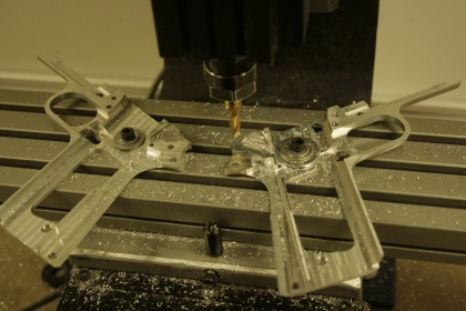
With the fire control group area widened out, the sear, disconnector, and hammer all fit nicely. The leaf spring and main spring housing also went in without problems, so now I had a functioning trigger. I then tried to fit the thumb and grip safeties and discovered another problem with the CAD model, which I probably would have noticed earlier if I had ever assembled a 1911 before. The hole for the thumb safety doesn’t go all the way through the frame like it should. So back on the mill to drill out the hole.
I also had to use a hand file to widen the hole where the thumb safety interacts with the hammer and trigger. Then I discovered with the full fire control group installed the slide won’t go all the way back.
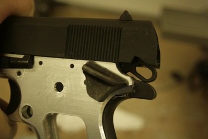
The hammer hits the top of the grip safety. It appears that the parts kit I ordered came with a mismatched hammer and grip safety. There are other style hammers that fit fine with that grip safety, and other style grip safeties that will fit with that hammer, but the ones I have don’t go together. I bought the parts kit over a year and a half ago, so its probably to late to do a warranty exchange. But a little work with a grinding wheel on the top of the grip safety and…
Next was tapping the holes for the grip screw inserts, which of course had to be some oddball-sized tap that I didn’t have, so I had to order a tap.
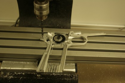
The grips themselves and the plunger tube fit with no issues. The last piece that needed to be attached to the frame was the ejector. Here, I discovered a third problem with the CAD model. One of the holes for the ejector was only half as deep as it should be. So back on the mill one more time.

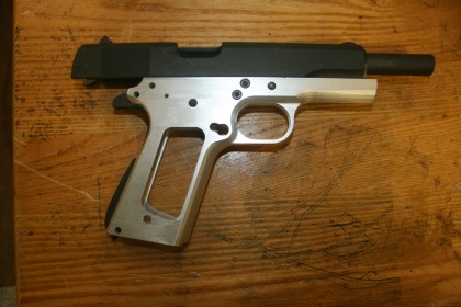
Now, with the ejector attached to the frame, the firing pin and extractor installed in the slide, and the slide and barrel back on the frame, I have a completed firearm.
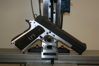
Everything seems to function correctly, and the headspace looks good. (I don’t need to buy a chamber reamer. Yay!) All that’s left to do is to decide how I want to “permanently” join the two frame halves. Currently, they are held together by just two bolts near the center of the frame. My original plan was to use an aluminum brazing rod to weld the two halves together, but looking at the finished frame I think if I add one more bolt in the top front of the trigger guard, and use a bolt instead of a pin to hold in the main spring housing it would work fine without welding.


Jason: could you email me? I would like to pick your brain about the CNC mill that you have. I currently have a Sherline vertical mill, and I have been seriously thinking of buying a CNC mill.
Does all this fitting work mean there are serious errors in the CAD model?
There were several, but from the sounds of it, talking to Jason while he’s been doing it, is that the 1911 isn’t quite as standardized as one might have thought.
I think it’s a combination of small errors in the CAD model, the cheap parts kit I bought, and the nature of the 1911 design itself. From what I understand even a build on a good commercial frame with high quality parts requires some fitting.
From what I’ve seen it does. I’ve got a Series 80 Colt that I’ve customized significantly. Basically everythingI bought labeled as “drop in” was not and required the use of my friendly neighborhood gunsmith for fitting purposes.
I’m convinced the majority of it stems from the design being developed in a time long before the modern super accurate processes we have today. That and the original Browning design was not all that “tight” in order to foster reliability on the battlefield….
The CT Lightguard for 1911’s is sold as only being guaranteed to fit on S&W and Kimber 1911’s. It drops onto my early ’90s Series 80 Colt LW Cmdr but I had to reprofile the triggerguard on my early ’80s Series 70 1911 to make it fit.
Both fit perfectly in all standard 1911 holsters prior and after.
I’m not sure if it is a cast versus machined issue(?), improved technology, bad QC, or just acceptable variation in manufacturing dimensions but it raised the same tolerance questions in me that your part’s kits have.
Understand all this, but I would have thought the fitting was mostly to the parts, not the frame. Interesting!
With a normal steel frame yes. In this case, especially because of the split frame and the mill, it was much easier to work with the large softer aluminum parts than the small harder steel ones. Since I was going for a plinking gun that goes bang reasonably reliably, rather than a match gun, it didn’t matter if at the end I ended up with things fitting a little loose.
Fun project,I’m sure Mr.Browning would be amused.
It’s really amazing to me sometimes how often I run into shooters who do not realize that you can’t mix “GI” profile grip safeties with rowel (“Commander”) hammers, nor can you mix beavertail grip safeties with GI profile hammers. . . even people who do their own (good quality) 1911 fitting. . .
Well, you can use a beavertail safety with a GI hammer if you bob the hammer, did it that way on my Springfield Armory 1911A1, mostly cuz I was too cheap to buy a new hammer and had already worked the original hammer and sear over for a better trigger pull. Might buy the ‘right’ hammer someday……
Thanks for the well written and informative post.
I milled an 80 percent AR lower quite a while ago. I don’t have a CNC mill, so I was going to do it the old way by counting handwheel turns and careful measurement. That didn’t work as well as I had hoped so before ruining the lower, I added a 3 axis DRO set. The starter drill mark in the wrong location is almost hidden by the safety.)
I just finished milling a polymer 80 percent lower. The machining was much easier than the first lower, and the lower is ready to test with a .22 long rifle upper. As you said, the parts kit went in with only a few minutes of work. The aluminum lower is still waiting for me to etch the identifier markings and anodize and probably dura coat.
I am sure my machining and gunsmithing skills are NOT up to a 1911 project……yet!
John in Philly
Did you use the same IGS solid model that CNCguns has on their website?
I was thinking of tossing a billet in my cnc to try the file out, but if it didn’t work on yours that well, I may pass.
That’s the model I used. I wouldn’t say it didn’t work out. Overall it worked out really well. The errors in the model are small, few, and easy to correct afterwards. None of them lead to material getting removed from the wrong place.
Thanks, I will give it a shot.
Nice build! You don’t happen to still have the cad or cam file of the frame cut in half do you? I don’t think I’m ready to tackle the solid frame yet. That magwell, trigger area, and barrel lug area They look like a bear on the original file, and I don’t think my mini mill has the headspace. I’d like to try the halves and weld them together.